
- All
- Product Name
- Product Keyword
- Product Model
- Product Summary
- Product Description
- Multi Field Search


Views: 0 Author: Site Editor Publish Time: 2026-07-19 Origin: Site


In the production of inductive devices, mechanical precision directly dictates electrical performance. Winding tension acts as a primary variable in long-term reliability. A wound core transformer relies heavily on exact tension parameters to function efficiently. Improper winding tension—whether too loose or too tight—introduces hidden inefficiencies. These include increased resistance, thermal hotspots, and compromised insulation. Such defects lead to premature field failures and operational disruptions.
Evaluating winding tension controls is a mandatory step for engineers and procurement teams when vetting suppliers. Ensuring the selected components meet strict operational tolerances prevents costly downstream issues. You must understand how tension interacts with core materials and winding structures to make informed sourcing decisions.
Efficiency vs. Resistance: Loose winding increases overall wire length, directly elevating resistance and unwanted copper losses.
Material Sensitivity: Optimal tension is required to prevent mechanical deformation of sensitive magnetic materials, preserving expected core loss values.
Thermal and Mechanical Stability: Precise tension control ensures maximum electromagnetic coupling while maintaining the structural integrity needed to withstand short-circuit fault currents.
Vendor Evaluation: Advanced tension monitoring separates a top-tier wound core transformer manufacturer from commodity suppliers.
Tight, consistent winding minimizes the physical gap between the primary and secondary coils and the core limb. This proximity is essential for efficient energy transfer. Manufacturers typically wind the primary and secondary coils directly over each other on a single core limb. This concentric arrangement maximizes electromagnetic coupling and significantly reduces stray magnetic flux. Precise tension ensures the layers remain compact, preventing air gaps that could disrupt the magnetic field. When you measure the leakage inductance on a poorly tensioned coil, the numbers spike immediately. The physical distance between the copper and the steel dictates the flux linkage efficiency. If the winding machine lacks dynamic tension control, the outer layers inevitably bulge, pushing the copper further from the core limb and degrading the transformer's voltage regulation capabilities.
The windings are wound around a non-conductive base known as a former or bobbin. This component provides structural support and insulation. However, it faces immense mechanical stress during the winding process. Excessive winding tension can warp, crack, or collapse the former. Such damage leads to axial misalignment, compromising the structural integrity of the entire coil assembly. Tension must be carefully calibrated to secure the wire without crushing the underlying support structure. In heavy-duty applications, formers made from high-density pressboard or fiberglass-reinforced epoxies are utilized. Yet, even these robust materials have yield points. If a machine operator sets the braking tension too high on a heavy gauge rectangular wire, the inward radial force will buckle the former long before the winding is complete, resulting in a scrapped unit.
Loose winding presents a significant trade-off. Even minor slack compounds over thousands of turns, significantly increasing the total wire length. This increased length mathematically increases DC resistance, an undesirable trait in inductive devices. Higher resistance leads directly to higher I²R (copper) losses. Consequently, the overall operating efficiency of the transformer drops, generating excess heat and wasting energy. Consider a standard distribution transformer: an extra 2% in wire length due to poor tensioning doesn't just add material cost; it permanently alters the load loss profile. Over a 20-year operational lifespan, that slight increase in resistance translates to massive energy waste. Engineering teams must specify maximum allowable resistance values during factory acceptance testing to catch these tension-related defects early.
Conversely, excessive tension poses severe risks to the insulation system. High tension causes mechanical thinning, scraping, or fracturing of insulating enamels and paper layers between concentric windings. The success criteria involve achieving maximum compactness and structural density without compromising the dielectric strength between adjacent turns. If the insulation fails due to over-tensioning, the risk of inter-turn short circuits increases dramatically. Kraft paper and Nomex insulation require specific compressive forces to maintain their dielectric ratings. When a wire is pulled too tight, especially around the rectangular corners of a core, the localized pressure can easily exceed the puncture resistance of the insulation. This creates a microscopic weak point that will eventually fail under electrical stress or lightning impulse surges.
Cold Rolled Grain Oriented (CRGO) steel possesses specific metallurgical properties designed for optimal magnetic performance along the rolling direction. However, this material exhibits extreme susceptibility to mechanical stress. Improper winding tension transmits compressive stress directly to the CRGO wound core. This stress induces magnetostriction and alters the delicate magnetic domain structure. As a result, the core experiences inadvertently increased core losses, commonly known as iron losses. The magnetic domains in CRGO steel are aligned during the manufacturing process to provide a low-reluctance path for the magnetic flux. When external mechanical pressure from tight windings squeezes the steel, these domains are forced out of alignment. You can actually hear the difference in the field; a highly stressed core will exhibit significantly louder humming due to increased magnetostriction.
Engineers utilize specific frameworks to calculate the maximum allowable compressive force the windings can exert on the core before magnetic degradation occurs. You must evaluate a manufacturer based on their material handling, assembly clamping, and stress-relief annealing processes. Proper annealing restores the magnetic properties after the core is formed, but subsequent winding must not reintroduce harmful stress. Balancing these forces is critical for maintaining the specified performance metrics.
Calculate the maximum radial inward force based on wire gauge and tension settings.
Compare the calculated force against the yield strength and stress-sensitivity curves of the specific CRGO grade.
Implement stress-relief annealing cycles immediately after core forming to reset the magnetic domain structure.
Utilize soft, compressible barrier materials between the core and the former to absorb excess winding pressure.
Conduct no-load loss testing before and after the winding process to verify that the tension has not degraded the core's magnetic properties.
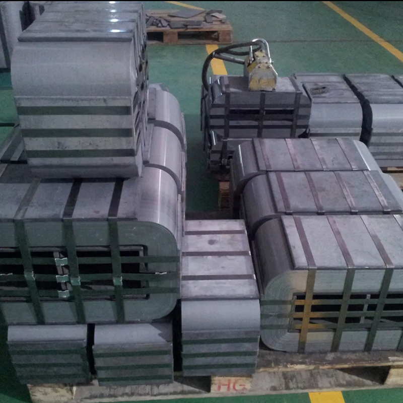
Winding tension directly impacts the physical construction's ability to handle heat. While tight winding improves electromagnetic coupling, it creates a dense mass that can trap thermal energy. This density must be balanced with the precise integration of cooling ducts. These ducts allow oil or air flow through the coil assembly, preventing thermal runaway and ensuring the transformer operates within safe temperature limits. If the tension is inconsistent, the cooling ducts can be crushed or blocked during the winding process. A blocked duct creates a localized thermal hotspot, accelerating the degradation of the surrounding insulation. Manufacturers must use rigid, precisely dimensioned spacers to maintain duct integrity while applying enough tension to keep the overall coil structure solid.
During short-circuit events, extreme radial and axial electromagnetic forces are generated within the transformer. Precise baseline winding tension is vital for survival under these conditions. Proper tension creates a rigid, cohesive physical mass that prevents coil deformation, telescoping, or mechanical collapse. A loosely wound coil lacks the structural integrity to withstand high-stress fault conditions, leading to catastrophic failure. The hoop stress exerted on the outer windings during a fault can easily rupture the coil if the initial winding tension was inadequate. By winding the copper tightly and curing the assembly with specialized resins, the entire coil becomes a monolithic block capable of resisting massive electromagnetic shocks.
Scaling up to a three phase transformer wound core multiplies the complexity of manufacturing. Maintaining uniform tension across three separate core limbs simultaneously requires advanced machinery and strict process control. Manufacturers face specific challenges regarding tension symmetry and alignment tolerances. These requirements are significantly more stringent for three-phase applications compared to single-phase units, demanding higher precision to ensure balanced electrical performance. If the tension varies between the phases, the resulting impedance mismatch will cause unbalanced voltage outputs and circulating currents. You must verify that the supplier utilizes synchronized, multi-axis winding machines capable of maintaining identical tension profiles across all three phases simultaneously.
A distributed gap wound core architecture offers distinct advantages in reducing exciting current and core loss. The core is constructed with precisely staggered gaps rather than a single cut. Winding tension must be meticulously controlled during assembly. Uneven or excessive tension can physically shift, overlap, or compress the staggered gap structure. Any disruption to this geometry negates the low-loss benefits of the design. The gaps are often only a few millimeters wide, and the interlacing pattern is highly sensitive to lateral forces. When evaluating a supplier, ask to see their gap inspection protocols post-winding. If they cannot prove that the gap structure remains intact after the coils are tensioned and clamped, their manufacturing process is flawed.
Requirements for a custom wound core often involve non-standard geometries, such as rectangular, stepped, or oval shapes. These form factors complicate uniform tensioning. You must evaluate a supplier's ability to adapt dynamic tensioning algorithms for bespoke designs. The equipment must adjust tension in real-time as the winding radius changes around non-circular cores to maintain consistent compactness without damaging the wire or the core. Winding a circular core is straightforward; the tension remains constant. However, winding a rectangular core means the wire speed and required tension fluctuate wildly as the winding head passes over the flat sides versus the sharp corners. Only advanced servo-driven systems can react fast enough to prevent wire snapping at the corners or slack pooling on the flats.
Wound core designs offer superior energy containment compared to traditional stacked-core alternatives. However, they present a trade-off regarding post-installation maintenance. Because the windings are tightly wound and physically harder to access or replace, field repairs are often impractical. Initial winding precision and tension control are therefore critical. High-quality manufacturing eliminates the need for future maintenance by ensuring long-term reliability from the start. You cannot simply unstack the top yoke to replace a damaged coil like you can with a stacked core. The entire unit is often sealed and treated as a single consumable asset. Therefore, the upfront quality control regarding winding tension is the only defense against premature failure.
Modern closed-loop, servo-driven tensioners featuring real-time load cells offer vastly superior reliability compared to legacy manual or friction-based braking systems. Automated systems adjust tension dynamically, compensating for wire variations and winding speeds. Procurement teams should request equipment lists and process control documentation during the vetting stage to verify the supplier utilizes modern, automated tensioning technology. Manual friction brakes wear down over time, meaning the tension applied at the start of a shift will differ from the tension applied at the end. Servo systems eliminate this variable entirely, providing a digital readout and a verifiable data log for every single coil produced.
Effective quality assurance requires rigorous in-process testing during the winding phase. Industry-standard evaluation lenses include dimensional checks, resistance measurements, and inter-turn insulation testing. You must verify that a manufacturer uses statistical process control (SPC) to monitor tension consistency across production runs. Consistent data collection ensures that every unit meets the specified tolerances.
Tension Condition | Physical Effect | Electrical Consequence |
|---|---|---|
Too Loose | Increased wire length, poor compaction, blocked cooling ducts | Higher resistance, increased copper losses, lower efficiency, thermal hotspots |
Optimal | Dense coil mass, intact insulation, precise gap alignment | Maximized coupling, high fault withstand, minimal losses, balanced impedance |
Too Tight | Insulation damage, core compression, former buckling | Risk of short circuits, increased iron losses due to stress, structural failure |
Partnering with a supplier lacking strict tension controls introduces significant downstream risks, including delayed commissioning and high failure rates. To mitigate these risks, implement a strict checklist. Require factory acceptance testing (FAT) to verify performance before shipment. Review historical failure data to gauge the supplier's track record. Finally, mandate specific winding tolerances and testing protocols directly in the procurement contract. Do not accept generic quality statements. Demand to see the actual tension logs for your specific production batch. If a supplier hesitates to provide this data, it indicates a lack of process control and a high probability of future field failures.
Winding tension is not a secondary manufacturing detail. It is a foundational metric that dictates the efficiency, safety, and longevity of the transformer. Selecting the right partner requires prioritizing a manufacturer who demonstrates transparent, automated tension control, deep material expertise, and rigorous QA testing.
Audit your current supplier's winding specifications and demand digital tension logs for all recent production batches.
Request detailed manufacturing process controls and equipment lists for your next RFQ to ensure they utilize servo-driven tensioners.
Contact technical sales for a custom engineering consultation to define exact dimensional and resistance tolerances for your specific application.
Mandate comprehensive factory acceptance testing (FAT), including no-load loss and short-circuit withstand tests, before authorizing any shipments.
A: Loose windings increase total wire length, which raises electrical resistance. This causes higher copper losses and reduces electromagnetic coupling, leading to poor efficiency and higher operating temperatures.
A: Excessive tension applies compressive mechanical stress to the CRGO steel. This stress distorts its magnetic domains, induces magnetostriction, and significantly increases core/iron losses.
A: Uneven or excessive tension can physically shift the precisely staggered gaps during manufacturing. This misalignment negates the design's low-loss benefits and degrades overall performance.
A: A former is the non-conductive base around which coils are wound. Excessive tension can warp, crack, or collapse the former, causing axial misalignment and structural failure.
A: Automated, servo-driven systems use real-time load cells to maintain exact tension continuously. This prevents insulation damage and ensures uniform coil density, unlike inconsistent manual braking systems.


