
- All
- Product Name
- Product Keyword
- Product Model
- Product Summary
- Product Description
- Multi Field Search


Views: 0 Author: Site Editor Publish Time: 2026-07-15 Origin: Site


Deploying an untested electrical unit poses severe operational and financial risks. Premature failure often stems from undetected manufacturing defects that compromise grid stability and site safety. Procurement and engineering teams must ensure that a newly manufactured unit meets exact design specifications, safety standards, and efficiency requirements before accepting delivery and assuming liability. Factory Acceptance Testing (FAT) serves as the critical evaluation gateway. This guide breaks down the mandatory routine tests, core-specific performance validations, visual inspection baselines, and vendor assessment frameworks required to verify transformer integrity. Skipping these validation steps leaves facilities vulnerable to catastrophic faults, unplanned outages, and massive replacement costs. By enforcing strict testing protocols, buyers shift the liability back to the manufacturer and guarantee the equipment will perform reliably under real-world electrical stresses.
Routine tests (TTR, Megger, Winding Resistance) are non-negotiable and must be performed on every single unit prior to shipment.
No-load loss and excitation current tests are critical for validating the efficiency of specific materials and designs, such as a CRGO wound core.
Pre-test visual inspections are the first line of defense, catching structural and mechanical defects before electrical testing begins.
Custom or highly specialized applications require Type and Special tests (e.g., temperature rise, partial discharge, sound level) to validate the initial engineering design.
A reputable wound core transformer manufacturer will provide transparent, traceable, and standards-compliant (IEEE/IEC) test reports for buyer review.
Defining the baseline success criteria for transformer procurement requires achieving specified voltage regulation, thermal stability, and minimal energy loss over a 20-30 year lifespan. A wound core transformer relies on continuous magnetic pathways, meaning any deviation in material handling directly impacts long-term performance. Unlike stacked cores, wound configurations demand specialized manufacturing processes to maintain the integrity of the grain-oriented steel.
Wound cores require precise manufacturing techniques, including exact tension control and proper stress-relief annealing. Pre-delivery testing exposes hidden flaws like shorted laminations, improper gap alignment, or residual mechanical stress that visual inspections cannot catch. Without these tests, internal defects remain dormant until the unit is energized under load, at which point they manifest as localized overheating, excessive vibration, or catastrophic dielectric breakdown.
All testing protocols must comply with recognized international standards, such as IEEE C57.12.00/C57.12.90 or IEC 60076. These frameworks establish objective pass/fail criteria, ensuring that performance metrics are evaluated against universal engineering benchmarks rather than internal vendor approximations. Adhering to these standards provides a legal and technical baseline for equipment acceptance.
Test Category | IEEE Standard Reference | IEC Standard Reference | Primary Objective |
|---|---|---|---|
Routine Tests | IEEE C57.12.90 | IEC 60076-1 | Verify manufacturing consistency and basic functionality on every unit. |
Type Tests | IEEE C57.12.00 | IEC 60076-2 | Validate the engineering design (e.g., thermal limits) on a prototype. |
Special Tests | IEEE C57.12.90 | IEC 60076-3 / 10 | Assess specific operational parameters like sound levels or partial discharge. |
Before any electrical voltage is applied, a physical integrity audit establishes the mechanical baseline of the unit. This prevents technicians from energizing a physically compromised unit, which could lead to test equipment damage or personnel injury. The visual inspection acts as the first quality control gate.
Inspectors must execute a systematic mechanical review. This includes a detailed assessment of weld quality along the tank, verification of paint or galvanization thickness using a mil gauge, checking torque markers on structural bolts, and ensuring the correct installation of ground straps. Any signs of poor workmanship at this stage often indicate deeper quality control issues on the production floor.
Inspect all tank welds for porosity, undercutting, or incomplete fusion.
Measure coating thickness at multiple points to ensure compliance with environmental protection specifications.
Verify that all structural bolts are marked with torque paint, indicating they have been tightened to the correct foot-pound specification.
Check the alignment and secure fastening of core grounding straps.
Examine cooling fins or radiators for transit damage, bending, or blocked airflow paths.
Inspectors must verify all bushings and connections. Ceramic or polymer bushings are examined for micro-fractures, chips, and surface contamination. Technicians confirm correct torque-tightening values on all terminal connections to prevent high-resistance hotspots during operation. A loose internal connection will fail the subsequent winding resistance test, but catching it visually saves testing time.
Auxiliary and nameplate verification serves as the final mechanical check. Inspectors cross-reference nameplate data, including schematics, vector groups, and impedance values, against the approved design documentation for absolute accuracy. Any discrepancy here dictates an immediate halt to the testing process, as the unit may have been built to the wrong specifications.
Technicians measure the DC resistance of all windings at a known temperature using a highly accurate micro-ohmmeter. This test utilizes a four-wire Kelvin bridge method to eliminate the resistance of the test leads, providing exact measurements of the copper or aluminum conductors. The test verifies the integrity of internal connections, detects loose crimps or cold welds, and provides the baseline data needed to calculate load losses.
Because resistance changes with temperature, all readings must be corrected to a standard reference temperature (usually 75°C or 85°C) using established formulas. Results between phases must align closely. Typically, resistance values should show no more than a 1-2% deviation across phases. Significant variances indicate internal connection faults, variations in conductor cross-sections, or improper tap changer contact pressure.
This test applies a high DC voltage (typically 1000V to 5000V depending on the winding class) to measure the resistance of the insulation system between individual windings and ground. Low insulation resistance strongly indicates moisture ingress, surface contamination, or physical damage to the insulation paper during assembly. Technicians use a guard terminal to bypass surface leakage currents, ensuring the meter only reads the true volumetric insulation resistance.
Insulation resistance must meet minimum temperature-corrected gigaohm values. Furthermore, the Polarization Index (PI) ratio, calculated by dividing the 10-minute reading by the 1-minute reading, must meet specific standards. A PI of 2.0 or higher is generally required for Class B, F, or H insulation systems. A flat PI curve (a ratio near 1.0) suggests the insulation is saturated with moisture or conductive contaminants.
The TTR test applies a low AC voltage to one winding while measuring the output on the other winding. This confirms the exact turns ratio across all tap positions, ensuring the unit will step up or step down voltage exactly as designed. Modern TTR meters also measure the phase angle deviation between the primary and secondary voltages, which should be near zero for standard configurations.
The measured ratio must fall within the strict standard tolerance of ±0.5% of the calculated nameplate ratio. Failing this test indicates shorted turns, incorrect winding counts, or improper tap changer connections. If a unit fails the TTR test, it cannot be deployed, as it will output incorrect voltages and potentially damage downstream equipment.
Verifying vector groups and phase displacement is mandatory, particularly when integrating a three phase transformer wound core into an existing grid or preparing it for parallel operation. This test ensures the phase angles match the system requirements, utilizing clock-face notation (e.g., Dyn11 means the low voltage leads the high voltage by 30 degrees).
There is zero-tolerance for deviation from the specified vector group. Incorrect phase relations will cause severe fault currents, circulating currents, and immediate breaker tripping upon commissioning. Technicians verify this by applying a three-phase low voltage and measuring the voltage vectors between specific primary and secondary terminals to confirm the geometry matches the nameplate diagram.
This procedure involves energizing the low-voltage winding at rated voltage and frequency while keeping the high-voltage winding open-circuited. It measures the energy required to magnetize the core and the continuous losses present whenever the unit is energized. Technicians use precision wattmeters and average-voltage voltmeters to ensure the test voltage waveform does not skew the results.
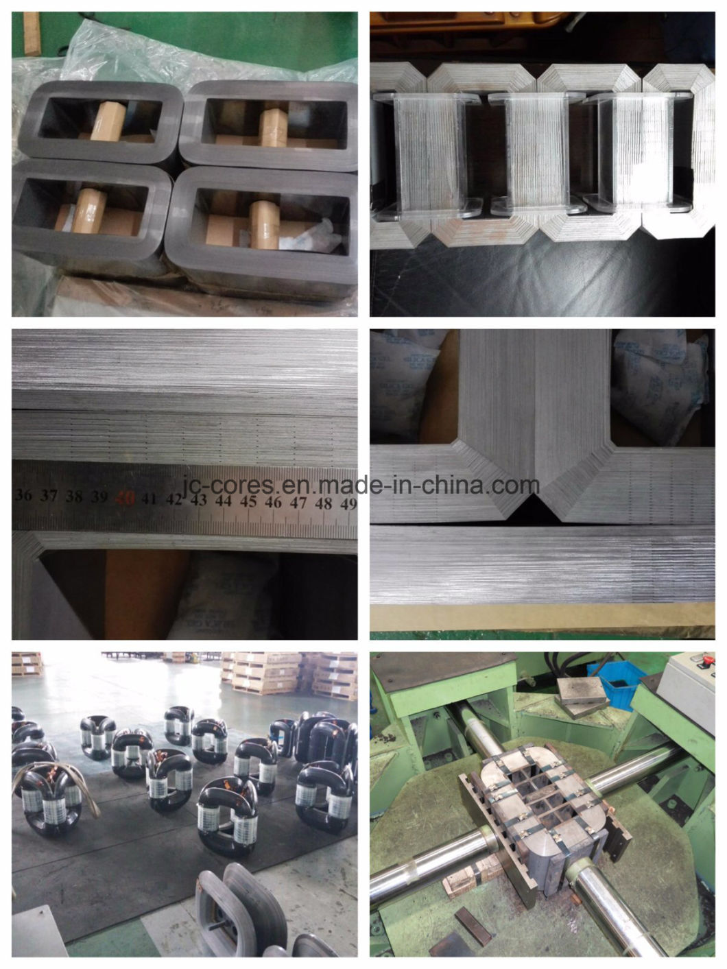
This test specifically validates the quality of a CRGO wound core. It verifies that the distributed gap wound core assembly was manufactured without inducing excessive mechanical stress or magnetic reluctance, which would otherwise spike excitation current. Proper annealing and careful handling of the steel laminations are proven during this exact test.
No-load losses must not exceed guaranteed values by more than the standard-specified margin. Depending on IEEE/IEC specifications, this is typically a +10% maximum allowable variance for individual units. High excitation current often points to a poorly assembled core joint or shorted core laminations.
The short-circuit test determines the impedance voltage and load losses at rated current. The low-voltage winding is short-circuited using massive copper busbars to minimize external resistance, and a reduced voltage is applied to the high-voltage winding until the rated current flows through the circuit. The power consumed during this test represents the copper losses and stray losses in the structural components.
These metrics directly connect to the transformer's operational efficiency, necessary cooling requirements, voltage regulation under full load, and overall short-circuit withstand capabilities. High load losses indicate inefficient winding designs, inadequate conductor sizing, or excessive eddy currents circulating in the tank walls and clamping structures.
Loss Parameter | IEEE Tolerance Limit | IEC Tolerance Limit | Root Cause of Failure |
|---|---|---|---|
No-Load Losses | +10% of specified | +15% of specified | Poor core steel quality, mechanical stress, bad joints. |
Total Losses (No-Load + Load) | +6% of specified | +10% of specified | Undersized conductors, high eddy currents, poor winding tension. |
Impedance Voltage | ±7.5% (two-winding) | ±7.5% to ±10% | Incorrect winding geometry, wrong turn counts. |
The applied voltage test applies a high AC voltage, significantly above normal operating voltage, between one winding and all other windings grounded to the core and tank. This stresses the major insulation structure, including the barriers between the primary and secondary coils and the standoff insulators. For example, a 34.5kV class winding might be tested at 70kV.
The insulation system must withstand this overvoltage for a specified duration, usually 60 seconds. Success is defined by the absence of insulation breakdown, arcing, or sudden leakage current spikes during the test window. A failure here usually results in a loud audible discharge and requires a complete teardown of the active part to locate the punctured insulation.
This test applies twice the rated voltage at a higher frequency (often 100 Hz to 400 Hz) to prevent core saturation. It stresses the turn-to-turn and layer-to-layer insulation within the windings themselves, rather than the insulation to ground. By increasing the frequency, the core can handle the double voltage without drawing massive magnetizing currents.
The duration of the induced test is typically 7200 cycles or 60 seconds, whichever is shorter. This test is highly effective at finding microscopic pinholes in the magnet wire enamel or tears in the layer insulation paper that occurred during the winding process.
Measuring the dielectric losses in the insulation system provides a critical baseline for future maintenance. The dissipation factor indicates the overall dryness and quality of the insulation system. Technicians apply a test voltage (usually 10kV) and measure the phase angle of the resulting current.
High power factor readings suggest moisture absorption, uncured resins, or contamination within the dielectric materials. For new oil-filled units, the power factor should typically be below 0.5%. Tracking this metric over the lifespan of the equipment allows maintenance teams to predict insulation degradation before a catastrophic failure occurs.
A temperature rise test is a Type test typically required for the first unit of a new design or a custom wound core. It simulates full-load conditions to verify that operating temperatures remain within the specified insulation class limits. Technicians use the short-circuit method, injecting total loss power into the unit until the top oil and average winding temperatures stabilize.
Once thermal equilibrium is reached, the power is cut, and winding resistance is measured rapidly as the unit cools. This data is extrapolated back to the exact moment of shutdown to determine the maximum winding hotspot temperature. Failing this test means the cooling system (radiators, fans) is inadequate for the core and coil design.
For liquid-immersed units, technicians establish Dissolved Gas Analysis (DGA) baselines and perform physical oil quality testing, checking dielectric breakdown voltage, moisture content (measured in parts per million), and acidity. Taking a baseline DGA before shipment ensures that any gases generated during FAT are documented and not mistaken for active faults during future field testing.
For dry-type units, Partial Discharge (PD) testing is utilized to ensure the cast resin or vacuum-pressure impregnated (VPI) insulation is free of localized internal voids. PD testing measures microscopic electrical discharges within the insulation structure in picocoulombs (pC). High PD levels will slowly erode the insulation over time, leading to premature breakdown.
Verifying acoustic noise limits is necessary for urban or indoor installations where strict decibel restrictions apply. The unit is energized at rated voltage in a quiet environment, and sound pressure levels are measured at specific intervals around the perimeter. Wound cores generally exhibit lower noise levels than stacked cores due to the absence of air gaps in the magnetic circuit.
Pressure and leak testing, utilizing helium or nitrogen envelope tests, ensures the absolute integrity of the tank, gaskets, and seals. The tank is pressurized to a specific PSI and held for 12 to 24 hours. A drop in pressure or the detection of tracer gas around the welds indicates a leak that will eventually allow moisture into the tank or insulating fluid out into the environment.
Evaluate a manufacturer based on their testing infrastructure. A credible wound core transformer manufacturer will utilize calibrated equipment, automated test bays, and hold third-party laboratory accreditations. Request and review certified, serialized test reports before authorizing shipment. The test reports must list the specific serial number of the unit, the test equipment used, the calibration dates of that equipment, and the exact environmental conditions during the test.
Accepting generic or "type" test data in lieu of unit-specific routine test data introduces massive implementation risks. Contractually mandate FAT witness hold points, either in-person or virtual. Specify clearly that failure to meet IEEE/IEC tolerances requires immediate rework and re-testing entirely at the vendor's expense. Do not accept units that require "field modifications" to pass baseline performance metrics.
Comprehensive pre-delivery testing remains the only empirical method to guarantee a transformer's safety, efficiency, and strict adherence to design specifications. Disqualify vendors who treat testing as an afterthought or refuse to provide detailed, serialized test reports for your specific units.
Integrate specific IEEE/IEC testing requirements directly into your next Request for Proposal (RFP).
Request sample FAT reports from prospective manufacturers to verify their documentation standards.
Establish contractually binding witness hold points for critical routine and type tests.
Ensure all test equipment calibration certificates are valid and attached to the final FAT documentation.
A: Routine tests are performed on every single manufactured unit to verify baseline manufacturing quality and detect defects. Type tests are performed on a prototype or the first unit of a specific design to validate the overall engineering and thermal design.
A: The distributed gap design minimizes magnetic reluctance across the core structure. During testing, this efficiency reflects as significantly lower excitation current and lower no-load losses compared to traditional butt-lap stacked cores.
A: TTR is a routine test that confirms the exact ratio of primary to secondary turns within the windings. It ensures the transformer will deliver the correct output voltage across all tap changer positions.
A: It verifies that the internal insulation system has not been compromised by moisture ingress, dirt, or mechanical damage during the assembly process, preventing catastrophic short circuits upon energization.
A: Type tests can be waived if the manufacturer provides historical, certified type test reports for an identical design built previously. However, routine tests are mandatory and can never be skipped.
A: The primary international standards dictate test procedures and tolerances. IEEE C57.12.90 is standard for North America, while IEC 60076 governs international markets.


