
- All
- Product Name
- Product Keyword
- Product Model
- Product Summary
- Product Description
- Multi Field Search


Views: 0 Author: Site Editor Publish Time: 2026-07-21 Origin: Site


Misaligned specifications in transformer manufacturing carry high financial and operational costs. When core dimensions or material properties deviate from the electrical design intent, the result is increased core losses, physical fitment failures, and delayed production timelines. Standard datasheets are insufficient for specialized applications. Precise technical drawings bridge the gap between engineering intent and manufacturing reality, ensuring the final product meets exact magnetic and spatial requirements.
Transitioning a custom design from engineering to production requires a comprehensive set of technical drawings, dimensional tolerances, and material specifications. A complete drawing package eliminates ambiguity. It allows production teams to build a wound core transformer that performs exactly as simulated. This guide details the specific documentation needed to ensure successful fabrication and assembly on the shop floor.
Accurate dimensional drawings (Inner Diameter, Outer Diameter, Height) specified to millimeter-level precision are the baseline, but mechanical tolerances dictate the success of the final assembly.
Specifying the exact gap configuration, particularly for a distributed gap wound core, is critical for controlling excitation current and minimizing localized heating.
Material callouts must go beyond generic labels to specify exact grades (e.g., specific CRGO wound core materials), interlaminar insulation coatings, and required magnetic performance metrics.
Partnering with an experienced wound core transformer manufacturer requires submitting holistic documentation that includes clamping, banding, post-annealing treatments, and environmental ratings.
A complete drawing package serves as the ultimate source of truth on the production floor. It must include precise dimensional accuracy, clear material callouts, specific processing instructions, and environmental compliance parameters. Without these elements, manufacturers are forced to make assumptions. Assumptions lead to variations in core geometry. These variations directly impact the magnetic and mechanical viability of the final product.
In field applications, a drawing missing a simple corner radius specification can halt an entire assembly line. Production engineers need exact numbers to program slitting and winding machines. When you provide a comprehensive drawing, you establish a clear baseline for quality control and incoming inspection.
Minute deviations in core geometry directly influence flux density distribution and no-load losses. If the cross-sectional area is smaller than designed due to poor tolerance control, the core will operate at a higher flux density. This increases both core loss and excitation current. Conversely, if the core is oversized, it wastes material and increases the overall footprint.
Precise drawings ensure the magnetic path length and cross-section match the theoretical calculations used during the design phase. For example, a 2mm deviation in the build height can alter the magnetic reluctance enough to push the transformer out of its specified efficiency class. Documenting the exact active cross-sectional area prevents these performance drops.
Implementation realities often reveal that a core meeting electrical specifications can still fail mechanically. If coil window clearances, winding radii, or thermal insulation allowances are not properly documented, the copper or aluminum coils simply will not fit. Interference between the core and the windings damages insulation, creating immediate short-circuit risks.
Detailed drawings account for the physical space required for bobbins, cooling ducts, and winding bulges. When winding heavy-gauge copper, the corners tend to bulge outward. If the core window drawing does not account for this mechanical reality, the assemblers will have to force the core halves together, damaging the laminations and degrading the magnetic properties.
The foundation of any custom wound core drawing is the exact specification of the Inner Diameter (ID), Outer Diameter (OD), and build height (H). These measurements must be specified to millimeter-level accuracy to ensure proper coil fitment. The ID dictates the available window area for the windings, while the OD and height define the overall physical envelope.
Drawings must explicitly document acceptable plus/minus tolerances for manufacturing variations. A typical tolerance might be +1.0mm / -0.0mm on the ID to guarantee the coil will always clear the core, and +0.0mm / -1.0mm on the OD to ensure the core fits within its designated enclosure. Failure to specify these directional tolerances often results in interference with the coil winding window.
Define the absolute minimum Inner Diameter required for the coil bobbin to slide through without friction.
Establish the maximum Outer Diameter to ensure the core does not contact the transformer tank or enclosure walls.
Specify the build height tolerance to align with the clamping structure and prevent loose laminations.
Specifying the inner and outer corner radius prevents mechanical stress on the windings. Sharp corners can cut through winding insulation during assembly or thermal expansion. Furthermore, tight radii cause localized magnetic flux crowding, which generates hot spots and increases core loss. Drawings must define a minimum corner radius suitable for the chosen lamination thickness.
Detailing the window area involves more than just the ID. The drawings must guarantee sufficient space for insulation layers, cooling ducts, and the conductors themselves. Engineers must account for the actual build-up of the coil, including the wrapping tape and varnish, ensuring the specified window clearances accommodate the final assembled dimensions.
The packing factor, or space factor, defines the ratio of active magnetic steel to the physical volume of the core. Specifications for ribbon tension and layer packing factor typically target a 95% to 97% space factor. If the tension is too low, the core will suffer from structural sag and reduced magnetic cross-section. If it is too high, the interlaminar insulation may be crushed.
Drawings must also outline strip-edge burr limit tolerances. Excessive burrs created during the slitting process can pierce the interlaminar insulation, causing short circuits between adjacent layers. Specifying a maximum burr height (e.g., less than 10 microns) prevents these interlaminar shorts and maintains the intended eddy current resistance.
Dimension Parameter | Typical Tolerance Range | Manufacturing Implication |
|---|---|---|
Inner Diameter (ID) | +1.0mm / -0.0mm | Ensures coil bobbin clearance. |
Outer Diameter (OD) | +0.0mm / -1.0mm | Prevents enclosure interference. |
Build Height (H) | +/- 0.5mm | Maintains clamping pressure consistency. |
Corner Radius | Minimum 2.0mm | Prevents insulation damage and flux crowding. |
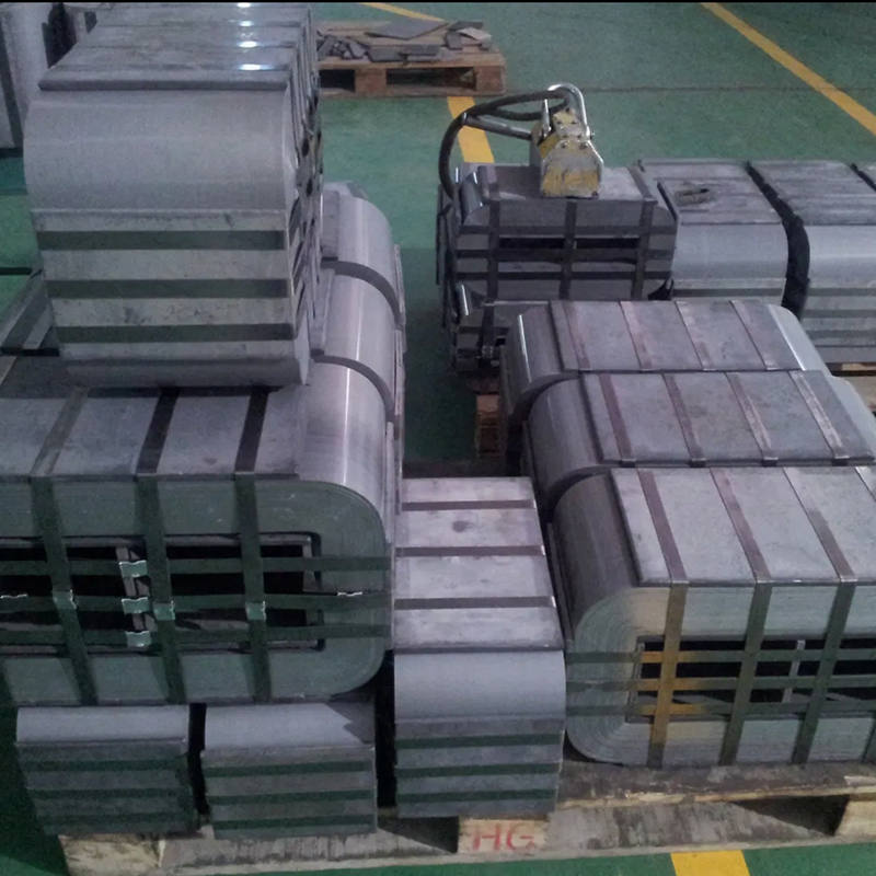
Detailed cross-sectional drawings are necessary to map out the step-lap or distributed gap patterns. A distributed gap wound core relies on precise gap placement to maintain structural integrity while managing magnetic reluctance. The drawings must show the exact overlap distance and the sequence of the step-lap.
Precise gap drawings mitigate fringing flux, which can cause localized heating in adjacent components. By controlling the gap distribution, engineers reduce local eddy current losses and lower audible noise levels. The evaluation dimension of gap placement must be explicitly detailed, showing how the gaps are staggered across the core build. You must specify the number of laminations per step and the total length of the distributed gap region.
Drawing requirements differ significantly between core-type and shell-type configurations. In a core-type design, the windings surround the core limbs, requiring clear specifications for the limb dimensions and yoke transitions. In a shell-type design, the core surrounds the windings, placing strict constraints on the inner window dimensions and the assembly sequence.
For nested-loop designs, where multiple wound loops are assembled to form the magnetic circuit, the drawings must detail the interface between the inner and outer loops. Tolerances here are critical. Any air gap between the nested loops will drastically increase the excitation current and degrade overall performance. The drawings must show how the loops are banded together to eliminate these parasitic air gaps.
Structural drawings for a single-phase core usually involve simple cruciform or rectangular shapes. In contrast, a three phase transformer wound core requires complex geometric callouts. Whether using an Evans core, a 3-limb, or a 5-limb configuration, the spatial relationship between the phases must be exact.
Multi-phase designs require specific callouts for phase-to-phase clearances, yoke cross-sections, and balanced magnetic path lengths. If the magnetic path lengths are asymmetrical, the transformer will exhibit unbalanced phase currents. Drawings must detail the exact spacing and alignment required to achieve magnetic symmetry across all three phases. You must also include the specific banding requirements to hold the multi-limb structure rigid during transport and operation.
Generic material labels are insufficient. Drawings must document the exact Cold Rolled Grain Oriented steel grade directly on the manufacturing notes. Specify whether the design requires conventional M-grades, high-permeability Hi-B steel, or domain-refined laser grades. Each grade offers different core loss characteristics and permeability curves.
Lamination thickness involves a trade-off between core loss and manufacturing cost. A 0.23mm CRGO wound core will have lower eddy current losses than a 0.27mm core, but it requires more layers and longer winding times. The drawing must specify the required thickness and the interlaminar insulation class, such as an inorganic C-5 coating, designed to withstand high annealing temperatures without degrading.
Specification Parameter | Standard Requirement | Field Impact on Performance |
|---|---|---|
Material Grade | Specific CRGO Grade (e.g., 23ZH90) | Determines baseline permeability and hysteresis loss. |
Lamination Thickness | 0.23mm, 0.27mm, 0.30mm | Directly controls eddy current losses at operating frequency. |
Insulation Coating | C-5 or C-6 Inorganic | Prevents interlaminar shorts during high-temp stress relief annealing. |
Burr Limit | < 10 microns | Prevents physical puncture of the insulation coating. |
Electrical testing parameters must be included within the drawing's notes section to establish clear quality acceptance criteria. Specify the maximum operating flux density in Tesla and the maximum allowable core loss in Watts/kg or Watts/lb at specific frequencies, typically 50Hz or 60Hz.
Providing these targets allows the manufacturer to verify the core's performance before shipping. If the core fails to meet the specified core loss at the target flux density, it indicates a problem with the material batch, the winding tension, or the annealing process. Clear targets prevent substandard cores from reaching the assembly line. Specify the testing method, such as Epstein frame testing or single-sheet testing, to ensure consistent measurement standards.
The thermal class (e.g., Class H, Class R) and environmental operational limits must be specified directly in the drawing legend. These ratings dictate the types of banding materials, adhesives, and protective coatings the manufacturer can use. Materials that degrade at high temperatures will compromise the core's structural integrity over time.
For specialized environments, drawings must map interfaces for specific protections. This includes hermetic sealing requirements for underwater or subsea transformers, or corrosion-resistant epoxy coatings for marine installations. Environmental specifications ensure the core survives its intended operational lifecycle without premature degradation. If the core will be submerged in oil, specify that all adhesives and resins must be oil-compatible to prevent contamination.
Mechanical drawings must show exactly where steel, copper-alloy, or resin banding will be applied to maintain core integrity. Banding holds the laminations tightly together, preventing vibration and noise. However, the drawings must explicitly instruct how to apply metallic banding without creating a closed electrical loop, which would act as a shorted turn and cause catastrophic heating.
Clamping structures, torque limits, and ground strap pathways must also be detailed. Proper grounding provisions are essential to prevent floating potentials on the core structure. The drawings should specify the exact location for grounding tabs and the required torque for clamping bolts to ensure the core is held securely without distorting the laminations. Over-torquing the clamps will introduce mechanical stress, which degrades the magnetic properties of the CRGO steel.
The core winding process introduces internal mechanical stresses into the steel, which severely degrades its magnetic properties. Drawings must document the thermal profile requirements for stress-relief annealing cycles. This typically involves heating the core to around 800°C in a protective nitrogen or hydrogen atmosphere, holding it at temperature, and cooling it at a controlled rate.
Following annealing, edge-bonding or epoxy impregnation processes are often required to ensure environmental resilience, structural rigidity, and low vibration. The technical drawings must specify the type of resin, the required penetration depth, and the curing temperature to ensure the core remains a solid, unified structure during operation. Specify whether vacuum pressure impregnation (VPI) is required to achieve the necessary resin penetration.
Specify the peak annealing temperature and the required hold time.
Define the atmospheric gas mixture required during the annealing cycle to prevent oxidation.
Detail the cooling rate to prevent the reintroduction of thermal stresses.
List the approved resin types for edge-bonding or full impregnation.
Assessing a custom manufacturer requires evaluating how they interact with your technical drawings. A competent wound core transformer manufacturer will not simply accept a drawing and begin production. They will conduct a thorough engineering review to ensure all specifications are clear, achievable, and optimized for their specific winding and cutting equipment.
You should expect the manufacturer to return redlined drawings with proposed tolerance adjustments based on their machine capabilities. This back-and-forth communication is a sign of a mature engineering department. If they accept a complex drawing without a single question, they are likely ignoring the finer details and planning to build the core using their standard, non-customized processes.
Warning signs include a manufacturer accepting incomplete dimensional sketches without requesting tolerance limits. If they do not ask for packing factor expectations or material grade clarifications, they are likely making assumptions that will compromise the final product. A lack of questions regarding annealing profiles or testing parameters indicates a lack of rigorous quality control.
Another major red flag is the inability to provide material test certificates for the specific CRGO steel batch used in your cores. If the manufacturer cannot trace the steel back to the mill and verify its magnetic properties before winding, you cannot guarantee the performance of the final transformer.
A valuable manufacturing partner conducts a formal Design for Manufacturability (DFM) review. They will identify potential mechanical interference issues before production begins. Furthermore, they will suggest optimizations, such as adjusting the corner radius for better material yield or recommending a different step-lap pattern for core loss reduction. This collaborative approach ensures the highest quality outcome.
Look for manufacturers who offer prototype runs with full dimensional and magnetic inspection reports. A partner who provides a first-article inspection report detailing the exact ID, OD, height, and core loss of the prototype demonstrates a commitment to meeting your precise technical specifications.
Compile all technical requirements, including electrical targets, environmental ratings, and physical constraints into a single drawing package.
Review CAD models specifically for tolerance stack-ups, paying close attention to window clearances and corner radii.
Define exact material grades, lamination thicknesses, and required post-winding treatments like annealing and impregnation on the drawing notes.
Engage with a specialized manufacturer early in the process for a comprehensive Design for Manufacturability (DFM) consultation.
A: The interplay between the inner diameter (window area), build height, and corner radius is the most critical. These dimensions, along with their strict mechanical tolerances, dictate whether the physical copper or aluminum coils will clear the core without damaging the insulation during assembly.
A: You must provide cross-sectional diagrams detailing the exact overlap distance, the sequence of the step-lap pattern, and the individual gap length. This precise mapping ensures the manufacturer cuts and assembles the core to minimize fringing flux and localized heating.
A: A manufacturer requires the exact Inner Diameter, Outer Diameter, Height, acceptable dimensional tolerances, specific material grade, tape thickness, target core loss at a specific flux density, and the total required volume or weight.
A: Yes. Multi-phase designs add significant complexity. Drawings must specify multi-limb spacing, yoke dimensions, nested loop interfaces, and phase balancing parameters to ensure magnetic symmetry and prevent unbalanced phase currents during operation.
A: The specific material grade dictates the core's magnetic permeability and hysteresis loss. The interlaminar insulation class must be specified to ensure it can withstand high-temperature stress-relief annealing without degrading, which prevents eddy currents in the finished core.
A: Standard dimensional tolerances typically range from +/- 0.5mm to +/- 1.0mm depending on the core size. Overly tight tolerances drastically increase manufacturing costs and rejection rates without providing proportional performance or fitment benefits.
A: Core-type features windings around two limbs, requiring clear limb and yoke dimensions. Shell-type uses nested outer loops to shield the inner winding, requiring distinct assembly drawings that detail the tight interfaces and banding between the inner and outer magnetic loops.


