
- All
- Product Name
- Product Keyword
- Product Model
- Product Summary
- Product Description
- Multi Field Search


Views: 0 Author: Site Editor Publish Time: 2026-07-23 Origin: Site


Short-circuit events represent an inevitable operational reality in power distribution networks. These faults generate instantaneous electromagnetic forces that frequently reach hundreds of times the normal operating stress. When a secondary short-circuit occurs, the normal steady-state back-EMF and inductive impedance collapse entirely. The winding instantly turns into a near-dead short where current is limited only by leakage impedance. This physical reality results in a massive surge in peak current. Catastrophic transformer failure during such a fault is rarely an electrical breakdown first. It is typically a mechanical failure involving winding deformation, core shifting, or clamping structure collapse that ultimately leads to insulation rupture. To combat these extreme physical stresses, engineers rely on specific mechanical and magnetic architectures. A wound core transformer provides a targeted engineering solution designed to distribute and withstand these severe radial and axial forces. This evaluation details the structural mechanics of wound core technology for procurement and system design engineers.
Mechanical Rigidity: The continuous-strip construction of a wound core inherently resists the mechanical deformation caused by extreme radial and axial electromagnetic forces better than traditional stacked-core assemblies.
Optimized Flux Distribution: Utilizing a distributed gap wound core minimizes localized magnetic flux crowding, reducing vibration and mechanical stress during peak fault currents.
Material Efficiency: A CRGO wound core ensures optimal grain orientation alignment, providing superior magnetic performance while maintaining structural integrity under high thermal and mechanical loads.
Clamping Integrity: High-fault resistance depends on robust mechanical clamping structures (including pressure rings, tie rods, and core clamps) integrated directly with the core.
Vendor Accountability: Selecting a qualified wound core transformer manufacturer requires verifying their dynamic short-circuit withstand testing protocols and custom clamping structure designs.
Transformers must survive extreme mechanical stress during a fault. The baseline survival requirements depend heavily on the relationship between peak asymmetrical short-circuit current and the resulting physical forces exerted on the internal components. When a fault clears, the equipment must remain fully operational without internal deformation. We measure this survivability by analyzing the specific forces acting on the copper or aluminum conductors and the surrounding steel core.
The first half-cycle of an asymmetrical short-circuit current produces the maximum mechanical shock. During this dynamic phase, the physical forces scale with the square of the peak current. This initial impact tests the absolute tensile strength and clamping rigidity of the assembly. If the core clamps yield or the pressure rings bend during this first cycle, the transformer will fail regardless of thermal limits.
Following the dynamic shock, the thermal phase begins. Over several seconds, rapid thermal expansion occurs due to intense cumulative heating. This expansion compounds the mechanical stress, pushing components against their restraints and accelerating insulation degradation. The copper conductors heat up rapidly, expanding linearly and pushing against the top and bottom yokes.
Phase | Duration | Primary Stress Factor | Failure Mechanism |
|---|---|---|---|
Dynamic Phase | First half-cycle (approx. 10ms) | Peak asymmetrical current squared | Mechanical buckling, clamping failure, winding displacement |
Thermal Phase | 2 to 5 seconds | Cumulative I²R heating | Insulation melting, thermal expansion, conductor softening |
Fault currents generate destructive forces in multiple directions simultaneously. Radial forces create hoop stress, attempting to burst outer windings outward while simultaneously crushing inner windings inward against the core structure. If the core lacks internal rigidity, the inner winding will collapse inward, destroying the insulation barrier.
Axial forces attack the winding heights. They create severe compressive stress on internal conductors and expansive forces that bend pressure rings, tie rods, and core clamps. Any physical misalignment or uneven winding height amplifies these axial forces, creating a mechanical weak point that often leads to structural buckling.
Radial outward forces stretch the outer conductors, testing their tensile yield strength.
Radial inward forces compress the inner conductors against the core cylinder.
Axial compressive forces crush the radial spacers between winding discs.
Axial expansive forces push the entire winding block against the top and bottom clamping frames.
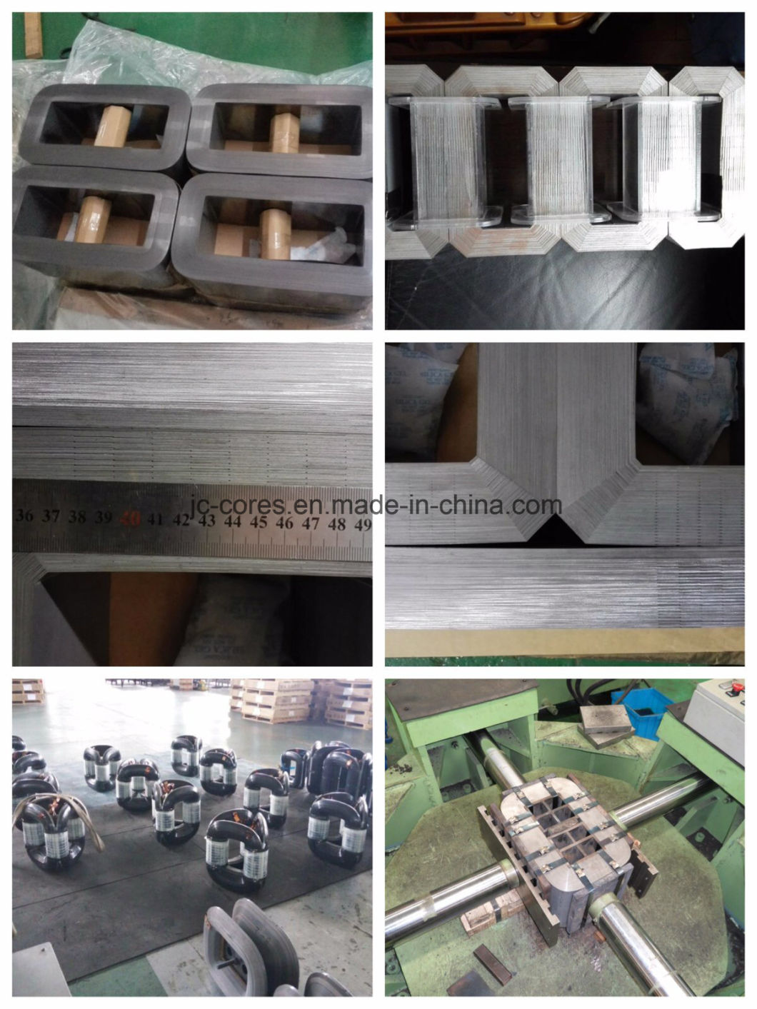
The physical geometry of a wound core offers distinct mechanical advantages over conventional stacked or laminated cores when subjected to severe fault currents. Stacked cores rely on interleaved joints that can slip or separate under extreme vibration. Wound cores eliminate this vulnerability entirely.
The continuous winding of steel strip eliminates the mechanical weak points and joint slippage commonly found in the interleaved joints of stacked cores. This seamless, closed-loop construction provides a naturally rigid internal bracing structure against radial crushing forces. The unbroken steel band maintains structural integrity even when subjected to extreme inward pressure from the windings.
When the inner winding experiences radial inward forces during a fault, it presses directly against the core. A stacked core can buckle inward if the laminations separate. A wound core acts as a solid, continuous cylinder, providing immense counter-pressure and preventing the inner winding from collapsing.
Cold-Rolled Grain-Oriented electrical steel provides critical mechanical durability. The continuous alignment of the grain in a CRGO wound core prevents localized hot spots and magnetic saturation points. By maintaining uniform flux distribution, the core minimizes the severe mechanical vibrations that exacerbate physical damage during a fault.
Properly annealed CRGO steel possesses high tensile strength. During the manufacturing process, the steel strip is wound under tension and then annealed to relieve internal stresses. This process locks the physical shape of the core, creating a hardened structure that resists deformation when hit by the dynamic shock of a short circuit.
A distributed gap wound core staggers the necessary cuts across the core build. This engineering approach prevents the formation of a single plane of mechanical weakness. By distributing the gaps, the core retains high tensile strength and ensures uniform clamping pressure under severe electromagnetic shock, preventing localized structural failure.
Core Type | Joint Structure | Mechanical Weakness | Short-Circuit Resilience |
|---|---|---|---|
Stacked Core | Interleaved corners | Joint slippage under vibration | Moderate (requires heavy external bracing) |
Single Gap Wound | One continuous cut line | Concentrated stress at the gap | High (but vulnerable at the cut plane) |
Distributed Gap Wound | Staggered cuts across build | None (stress is distributed) | Maximum (inherent structural rigidity) |
Wound core technology scales effectively to meet the demands of multi-phase industrial and utility applications, offering specific advantages during unbalanced fault conditions. Multi-phase systems introduce complex magnetic interactions during asymmetrical faults, requiring robust core geometries.
During single-phase-to-ground or line-to-line faults, a three phase transformer wound core must handle severe imbalances. Symmetrical, integrated flux paths found in 3D or Evans-type wound cores help balance magnetic forces. This symmetry prevents asymmetrical mechanical torquing on the active part, keeping the structure stable even when fault currents are unevenly distributed.
In a traditional planar core, an asymmetrical fault causes uneven flux distribution, leading to severe vibration and twisting forces on the core clamps. A 3D wound core distributes these forces evenly across its three identical core limbs, neutralizing the twisting momentum and protecting the winding blocks from shear stress.
Winding height uniformity remains a critical factor in short-circuit withstand capability. A three phase transformer wound core allows for tightly controlled winding geometries and highly precise, uniform winding heights that minimize axial displacement. External heavy-duty core clamps, pressure rings, and tensioning bolts establish a monolithic clamping system. This integrated approach prevents vertical winding shifting and secures the active part against destructive axial forces.
Measure and match the exact height of all three phase windings before assembly.
Apply hydraulic pressure to compress the windings to their final operational height.
Lock the tie rods and core clamps while the windings are under hydraulic compression.
Verify clamping torque specifications to ensure zero vertical tolerance.
Specifying transformers for environments with high available fault currents requires a careful evaluation of custom design parameters and mechanical bracing techniques. Standard off-the-shelf designs often fail to account for the specific fault capacities of heavy industrial grids or renewable energy tie-ins.
Engineers must balance voltage regulation against short-circuit current limiting. Specifying a custom wound core allows designers to tune the leakage inductance and short-circuit impedance precisely. This optimization limits fault currents to manageable levels without sacrificing steady-state operational efficiency.
By adjusting the physical distance between the primary and secondary windings (the leakage channel), engineers can increase the impedance. A higher impedance chokes the maximum fault current, directly reducing the mechanical forces exerted on the core and coils during a short circuit.
Integrating custom wound core designs with cast resin or Vacuum Pressure Impregnation technologies significantly enhances mechanical stability. Potting and encapsulation lock the windings directly to the rigid wound core. This process creates a monolithic structure highly resistant to electromagnetic shear forces, preventing winding movement during severe dynamic shocks.
When the resin cures, it fills all microscopic voids between the conductors and the core insulation. This solid mass transfers radial and axial forces directly into the steel core, utilizing the core's immense tensile strength to support the relatively softer copper or aluminum conductors.
Procuring advanced wound core technology involves specific commercial and practical realities that engineers must navigate to ensure operational resilience. Selecting the wrong vendor or specifying inadequate testing protocols leads to premature equipment failure.
Wound cores, especially distributed gap and 3D designs, require specialized manufacturing equipment. This complexity can increase initial lead times compared to standard stacked cores. However, this factor must be weighed against the financial risk of catastrophic failure in mission-critical applications where operational resilience is paramount. Facilities cannot afford extended downtime caused by a transformer tearing itself apart during a routine grid fault.
Evaluating vendors requires strict attention to empirical data. Engineers must request certified type-test reports for dynamic short-circuit withstand capability, adhering to IEC 60076-5 or IEEE C57.12.90 standards. Auditing the manufacturer's annealing processes is also critical, as improper annealing degrades the mechanical and magnetic properties of the CRGO steel. Furthermore, ensure the wound core transformer manufacturer provides detailed drawings of their clamping structures, including torque specifications and pressure ring material selection.
Demand physical type-test certificates from an independent high-power laboratory.
Audit the vendor's in-house core annealing furnaces and temperature control logs.
Review the engineering drawings for the core clamping frames and tie-rod sizing.
Verify the quality and origin of the CRGO steel used in the core build.
Calculate the maximum available fault current for your specific installation site before drafting procurement specifications. Define the required short-circuit impedance to limit fault currents effectively based on your grid capacity. Initiate technical dialogues with specialized manufacturers to request dynamic withstand test data for their specific core geometries. Review vendor clamping structure designs and annealing process certifications to ensure long-term mechanical reliability.
A: It staggers the magnetic gaps, eliminating a single continuous plane of mechanical weakness and distributing electromagnetic stress evenly across the core structure.
A: The dynamic phase occurs within the first half-cycle and subjects the transformer to peak mechanical shock and clamping stresses. The thermal phase occurs over several seconds and subjects the system to extreme heating and thermal expansion.
A: Yes, particularly 3D wound core designs, which provide symmetrical magnetic paths that prevent uneven mechanical torquing during unbalanced faults.
A: Imbalances in winding height amplify axial forces during a fault, causing physical deformation. Precise winding height control, supported by robust core clamps and pressure rings, minimizes these asymmetrical vertical forces.
A: Impedance acts as a current limiter. Custom designs allow engineers to specify an impedance value that chokes the maximum fault current to a level the mechanical structure can safely withstand.
A: Buyers should demand dynamic short-circuit withstand type-test certificates compliant with IEC 60076-5 or IEEE standards, proving the design has physically survived simulated fault conditions.
A: Yes. While primarily used for magnetic efficiency, properly annealed CRGO steel in a continuous wound configuration provides high tensile strength and resists the physical deformation caused by severe electromagnetic shocks.


