
- All
- Product Name
- Product Keyword
- Product Model
- Product Summary
- Product Description
- Multi Field Search


Views: 0 Author: Site Editor Publish Time: 2026-07-17 Origin: Site


In power distribution and high-frequency electrical applications, unmitigated iron losses result in excessive heat generation and degraded system efficiency. The primary mechanical defense against these losses is the precise specification of lamination thickness. Engineers and procurement teams must balance strict efficiency mandates against the escalating manufacturing complexities, mechanical fragility, and stacking factor penalties associated with ultra-thin steel strips. Understanding the inverse relationship between steel strip thickness and eddy current losses is a fundamental requirement for modern electrical design. This guide breaks down the physical mechanics, material trade-offs, and manufacturing realities required to specify the optimal wound core transformer for specific operational frequencies and load profiles. We will examine how lamination thickness dictates magnetic performance and detail the engineering controls necessary to prevent core degradation during the assembly process.
Eddy Current Mitigation: Eddy current losses are proportional to the square of the lamination thickness; reducing strip thickness from 0.27mm to 0.1mm drastically cuts high-frequency losses but introduces stacking factor challenges.
The Stacking Factor Trade-Off: Thinner strips require more insulation layers per unit of volume, which reduces the active magnetic cross-sectional area and can inadvertently increase the overall core footprint.
Material Synergy: The performance of a CRGO wound core relies not just on thickness, but on the precise control of grain orientation, distributed gap architecture, and post-winding annealing processes.
Vendor Capabilities: Specifying ultra-thin laminations requires a wound core transformer manufacturer with advanced slitting and burr-control capabilities, as edge burrs can bridge laminations and negate the benefits of thin strips.
Defining acceptable no-load iron losses depends entirely on your application requirements and regulatory efficiency standards. Every magnetic circuit wastes a specific amount of energy simply by being energized. You must establish a strict loss threshold before selecting materials. Engineers measure these losses in watts per kilogram. When designing a transformer, you must account for the continuous energy drain that occurs whenever the primary winding is energized, regardless of the secondary load. Setting the right success criteria involves analyzing the operational duty cycle and the specific harmonic content of the electrical supply.
Faraday’s Law of Induction dictates that changing magnetic fields induce circulating currents within conductive materials. In a solid steel block, these eddy currents flow freely, generating massive resistive heat. By slicing the steel into thin laminations coated with microscopic insulation, you restrict these current loops. The physical separation prevents the currents from building up across the entire cross-section of the core.
Eddy current loss scales mathematically with the square of the strip thickness. Cutting the thickness in half reduces the eddy current losses by a factor of four. The lamination acts as a physical resistor to localized current loops. However, you face a thermodynamic limit. You cannot eliminate eddy current losses completely. You can only manage them through micro-thin boundary insulation. When you specify a thinner strip, you force the induced voltage to drive current through a much higher resistance path, thereby lowering the total power dissipated as heat.
Eddy currents represent only one half of the core loss equation. The other half is hysteresis loss, which occurs due to the molecular friction of reversing magnetic domains during alternating current cycles. Adding 3% to 4.5% silicon to the steel increases bulk electrical resistivity. This works in tandem with thin laminations to stifle current flow. The silicon addition makes the steel more brittle, which requires careful handling during the winding process.
Thickness reduction primarily targets eddy currents. Conversely, material grade targets hysteresis. High-permeability, grain-oriented silicon steel allows magnetic domains to flip with minimal energy resistance. The alignment of the crystal lattice structure in the rolling direction means that the magnetic flux encounters very little reluctance. When you combine ultra-thin laminations with highly oriented grain structures, you achieve the lowest possible total core loss for high-frequency applications.
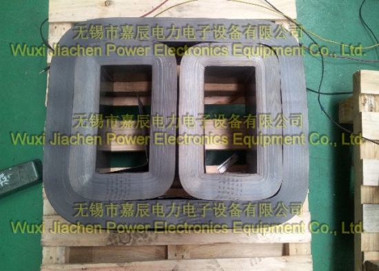
Selecting the correct thickness requires matching the material to the operating frequency. Using the wrong thickness leads to severe performance degradation or unnecessary manufacturing complications.
0.27mm to 0.30mm: This is the industry standard for 50/60Hz line frequency applications. It balances mechanical stability and acceptable loss profiles.
0.23mm: Engineers use this thickness for high-efficiency grid infrastructure and mild harmonic environments.
0.18mm: Often deployed in specialized aerospace or marine applications where weight and efficiency are strictly regulated.
0.10mm: Grain-oriented silicon iron steel at this thickness is reserved for high-frequency applications up to 200Hz and beyond, where eddy currents dominate the loss profile.
The stacking factor, or space factor, is the ratio of active magnetic steel to the total core volume. Thinner strips naturally increase the proportion of interlaminar insulation relative to the steel. A lower stacking factor requires a physically larger core to achieve the same magnetic flux density. This directly impacts the transformer footprint and increases the required copper winding volume.
When you design a core with 0.10mm steel, the insulation coating takes up a much larger percentage of the cross-sectional area compared to a 0.30mm core. You must compensate by increasing the core dimensions. This increases the mean length of the magnetic path, which slightly increases the total volume of steel required. You must calculate this trade-off carefully during the initial design phase.
Poor winding tension or strip surface waviness introduces micro air gaps between laminated sheets. Loose laminations yield higher no-load losses and lower magnetic permeability. They also cause severe audible noise due to magnetostriction. Precision tensioning during manufacturing is non-negotiable. If the winding machine fails to maintain consistent tension, the resulting core will have a spongy texture. This allows the individual laminations to vibrate against each other at twice the line frequency, generating unacceptable noise levels.
You must map strip thickness directly to your operating frequency. Specifying a 0.1mm strip thickness for a standard 50Hz application is an unnecessary complication. It provides diminishing returns and complicates the manufacturing process without delivering proportional energy savings. High-frequency inverters and traction transformers benefit immensely from ultra-thin steel, but standard distribution transformers do not.
Strip Thickness | Typical Application | Frequency Range | Stacking Factor Impact |
|---|---|---|---|
0.27mm - 0.30mm | Standard Distribution | 50/60Hz | High (Optimal space utilization) |
0.18mm - 0.23mm | High-Efficiency Grid | 50/60Hz (Harmonic) | Moderate |
0.10mm - 0.15mm | High-Frequency Systems | Up to 200Hz+ | Low (Requires larger core volume) |
Cold Rolled Grain Oriented steel relies on a highly aligned crystalline structure. The continuous winding process maximizes the magnetic properties of a CRGO wound core by aligning the flux path precisely with the grain orientation. This continuous path prevents the flux from crossing the grain, which would otherwise spike hysteresis losses. Unlike stacked cores where the flux must navigate corner joints and cross-grain regions, a wound core provides a seamless magnetic highway.
The manufacturing process for CRGO steel involves complex cold rolling and high-temperature annealing stages to develop the Goss texture. This texture ensures that the easiest axis of magnetization aligns with the rolling direction. When you wind this steel into a circular or rectangular core, you exploit this directional property to its maximum potential.
Gaps are necessary for coil assembly and managing magnetic reluctance. A distributed gap wound core minimizes localized flux crowding and fringing effects compared to concentrated gap designs. Ensuring tight step-lap joints is a critical balance. Large gaps between the strip ends in a distributed architecture yield significantly higher no-load losses and lower overall efficiency.
In a distributed gap design, the cuts in the steel strip are staggered throughout the core build. This prevents a single large air gap from forming. The magnetic flux can easily bypass a small cut by jumping to the adjacent overlapping lamination. This localized flux transfer does increase eddy currents slightly at the joint, but the overall reduction in reluctance far outweighs this minor penalty.
Three-legged designs introduce complex magnetic flux behaviors. Interlaminar flux transfer between adjacent core loops drives localized iron losses. In a three phase transformer wound core, flux jumps between the inner and outer rings. You must mitigate this through precise strip tensioning, thickness uniformity, and optimal overlap joint design to minimize cross-lamination flux leakage.
The geometry of a three-phase wound core typically involves two smaller inner loops and one larger outer loop that wraps around them. The areas where these loops meet experience complex flux interactions. If the laminations are not perfectly flush, the flux will jump across the interlaminar insulation, causing localized heating. Engineers must design the winding process to ensure absolute dimensional accuracy in these mating regions.
Ultra-thin, high-grade silicon steel requires a rigorous evaluation of long-term efficiency. You must calculate the energy savings from reduced no-load losses over the 20 to 30-year lifespan of the equipment. A highly efficient core reduces the continuous energy drain on the electrical grid. This efficiency translates directly into lower operating temperatures, which extends the life of the transformer insulation system.
When evaluating different core designs, engineers use capitalization formulas to assign a value to every watt of no-load and load loss. By comparing the capitalized loss values of a 0.23mm core versus a 0.27mm core, you can make an informed engineering decision based on lifecycle performance rather than just initial material specifications.
Specifying a custom wound core with non-standard strip thicknesses requires specialized tooling. Expect longer production cycles. The mechanical fragility of ultra-thin strips forces manufacturers to reduce winding speeds and implement strict handling protocols to prevent material tearing. Thin steel is highly susceptible to edge damage during the slitting process.
Manufacturers must adjust their uncoiler tension settings and use specialized guiding systems to handle 0.10mm or 0.15mm steel. If the tension is too high, the strip will stretch and lose its magnetic properties. If the tension is too low, the core will be loose and fail the dimensional tolerance checks. These manufacturing realities dictate the availability and production timelines for custom high-efficiency cores.
You must identify manufacturing defects that compromise core performance regardless of the specified thickness. Even the highest-grade steel fails if the assembly process introduces mechanical stress or electrical shorts. A thorough audit of the manufacturing facility is required to ensure they have the necessary process controls in place.
Verify the calibration records for all slitting and winding machinery.
Inspect the material handling equipment to ensure it does not induce bending stresses in the steel coils.
Review the quality control documentation for interlaminar insulation testing.
Examine the environmental controls in the winding area to prevent dust and debris from entering the core build.
Edge burrs present a critical risk. Microscopic metallic bridges between laminations create short circuits. These bridges allow massive eddy currents to flow, creating localized hot spots. You must evaluate a manufacturer based on their tooling tolerances, slitting blade sharpness, and maintenance protocols. A dull slitting blade will crush the edge of the steel rather than cutting it cleanly.
This crushing action destroys the interlaminar insulation at the edge of the strip and smears the steel, creating a conductive path between adjacent layers. High-quality manufacturers use tungsten carbide slitting knives and implement strict blade replacement schedules based on linear meters cut. They also employ continuous edge inspection systems to detect burrs before the steel reaches the winding machine.
The mechanical stress of winding degrades the magnetic properties of CRGO steel. Controlled-atmosphere annealing is absolutely necessary. This thermal process restores magnetic permeability and reduces hysteresis losses induced during the bending and cutting phases. The annealing cycle must be precisely controlled to prevent oxidation of the steel surface.
Manufacturers typically use a nitrogen-hydrogen atmosphere in their annealing furnaces. The temperature must ramp up slowly to around 800 degrees Celsius, hold for a specific duration based on the core mass, and then cool down at a controlled rate. If the cooling process is too rapid, it will reintroduce thermal stresses into the core, negating the benefits of the annealing cycle.
Evaluate the manufacturer's tension control systems. They must prevent interlaminar air gaps without over-stressing the thin steel strips. Inconsistent tension leads to a loose core, which vibrates violently under load and degrades efficiency. Modern winding machines use closed-loop servo systems to maintain exact tension profiles throughout the entire core build.
Demand rigorous factory acceptance testing for core loss. Compare Epstein frame testing data against whole-core testing results. Ensure verifiable compliance with IEEE, IEC, and NEMA standards before accepting the final product. The manufacturer must provide detailed test reports showing the exact no-load loss and exciting current at the specified magnetic flux density.
Steel strip thickness represents a calculated compromise between high-frequency eddy current suppression, stacking factor efficiency, and manufacturing viability. You must align your material specifications with the physical realities of core production and the specific electrical demands of your application.
Specify the core material thickness based strictly on the fundamental operating frequency and harmonic profile of the installation.
Calculate the stacking factor penalty when utilizing ultra-thin laminations to ensure the physical core dimensions fit within the required enclosure.
Audit the manufacturer's slitting process to verify strict edge burr tolerances and blade maintenance schedules.
Require documented proof of controlled-atmosphere annealing to guarantee the restoration of magnetic permeability after winding.
A: Solid metal cores allow massive, unconstrained eddy currents to circulate within the magnetic field. This generates extreme heat and severe energy loss. Thin, insulated strips restrict these currents to microscopic loops, drastically improving electrical efficiency.
A: For standard 50/60Hz power distribution applications, 0.27mm to 0.30mm is the industry standard. It provides the best balance of mechanical strength, acceptable core loss, and reliable manufacturing.
A: Thinner strips mean you need more individual sheets to build the same volume. Because each sheet has an insulation coating, the ratio of insulation to actual magnetic steel increases, lowering the overall stacking factor.
A: Edge burrs cut through the interlaminar insulation and physically connect adjacent steel sheets. This creates an electrical short circuit that allows eddy currents to flow across laminations, causing localized overheating and efficiency drops.
A: The physical processes of slitting and winding introduce severe mechanical stress into the steel. This stress disrupts the grain orientation and degrades magnetic permeability. Annealing relieves this stress and restores the material's magnetic properties.


